Richard Zhou
Opto-Mechanical Engineer

Lidar Projects


Lidar Near Field Artifacts & Mitigation
Both positive and negative objects misdetection are equally harmful
-
Near field point clouds artefacts are common challenges for variety of lidar sensor. The Minimum detection distance is a very important Lidar KPI.
-
Firmware artefacts suppression algorithm is industrial norm to mitigate the negative impacts of artefacts to perception. The suppression algorithm is not a lossless method which can cause false negative detection. The detection failure could be even more dangers. The suppression algorithm approach address the symptom, not the root cause.
-
The failure mode mechanism is investigated. Mitigation method by addressing the root cause of artefacts is explored.
-
A very simple solution of adding a small amount of dye into the lidar optical lens was proposed. the small percentage of ray attenuation of the dye suppress the near filed artefacts with minimum impact on the lidar long range detection ability.
Lidar PD Characterization Algorithem
Real world full range single and multi return PD evaluation
-
Objective: Develop a method to characterize the Lidar detection performance in real operation condition. Characterizes the PD and distance precision in all distance efficiently and accurately.
-
Currently the industrial have two ways to characterize the PD and range precision of Lidar:
-
Stop the beam scanning mechanism of the lidar, and test the PD at range finder mode. This is only the emission and receives loop PD performance at stationary. The influence of dynamic factors is not included. The data is misleading and not the real world point clouds data. The application algorithm and EOL calibration build upon the data set is not optimized.
-
Try to calculate the PD with very precise ground truth FOV by utilizes tremble scanner or other high precision instruments. It is only able to achieve reasonable result at short distance when large number of points on testing target. At longer distance, only few points on target, the result is not consistent and not useable. Also the setup is very time consuming and not practical to test multi distance and other test condition.
3. A test workflow and algorithm was developed to find out the PD and range precision by just capture the point clouds at different distance without special setup. Each distance only take few minutes and also works until the lidars maximum detection distance.


Reliability numerical modeling & Functional Safety
System reliability and functional safety design & Sub-system reliability budget allocation
vehicle system level reliability prediction
-
Data driven system design for functional safety and reliability.
-
Quantitative components reliability and functional safety assessment and selection of Lidar, radar and camera.
-
Establish quantitative system service life specs.
-
Allocate reliability beget for subsystem to establish reliability requirement of subsystem and functional team.
-
Optimize system reliability topology design.
-
Quantitative proof to support functional safety and reliability warranty spec.

System functional safety & reliability topology comparison

FIT Requirements: ASIL B <100
ASIL D <10

Photonics Projects
Blind spot free panoramic rear
view system
Windshield size rear view mirror
Blind spot free panoramic rear view system utilize the whole windshield as reflection mirror, since the reflection surface stretch from driver side mirror to passenger side mirrors and have a far larger reflection surface size than the traditional rear view mirror. All the views which can be observed in traditional central rear view ,driver , passenger side mirrors and blind spot zone can be seen in this single view.
Shadow-free outdoor video acquisition
Outdoor stable video aqusition
•Lab quality video at any ambient condition. free of interference of ambient lighting condition and out of FOV objects optical properties.
•Full loop dynamic range reduction. system only need to deal with native scene dynamic range of about 30 db instead of about 160 db all condition dynamic range. greatly increase the effective image data resolution and image classification accuracy.
•Much clean image data for any application which need to work at real world outdoor conditions.
•90% reduction of hardware and software resource requirement.
RCCC Sensor Color space
Design Intend
•RCCC color space was created to assess the chromatic ability of RCCC system.
•F=(C-R)/C represents color spaces as follow:
•The diagram represent only pure color conditions.
Optical traffic signs segregation
•Optical apparatus integrate car head lamp properties with special TSR sensor .
•The output images from this optical apparatus is basically get targets segregated and indentified by optical mean.
•Clean target images of day and night scene with much accurate color are provided for TSR algorithm.
•After the segregation and identification, TSR algorithm deals variables that have less unpredictable and have stricter mathematic rules to follow.
•TSR algorithm based on this optical apparatus can expect higher classification rate due to less uncertainty.
DMS Images Acquisition Apparatus
Driver monitoring Incabin image aqusition
•Virtual camera optical axis follow driver’s view direction
•No ROI blockage at normal vehicle operation condition which guarantee continues classification and tracking the features.
•50% brightness uniformity ratio
•Minimal DOF required(360mm)
•70% lower of sensor resolution and hardware computational power requirement
Expertise
Mechanical
Precision mechanical design

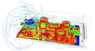
CFD simulation
Chips stress analysis


Hermetic package

TOSA/ROSA
Lead frame injection molding package
PCB level package


Dewar (Cryogenic) HgCdTe detectors

CNC operation and G coding

Optical
Optics alignment
Optics ray tracing
Algorithm optical math mold construction


Fiber optics sensor

Opto-Mechanical system architecture

Opto-electronics
Optical sensor characterization
MTF(resolution)
Color matrix tuning
Sensor response
(Dynamic range, S/N)


